FIT
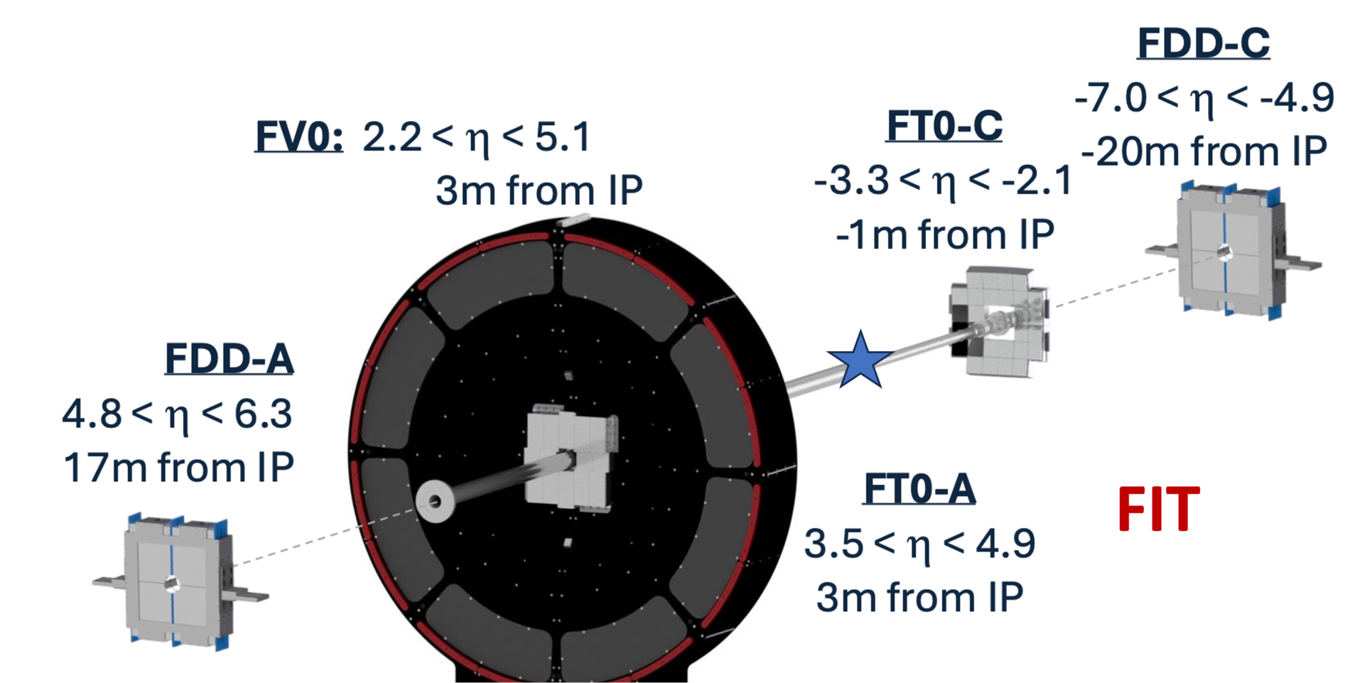
The Fast Interaction Trigger (FIT) serves as an interaction trigger, online luminometer, initial indicator of the vertex position, and the forward multiplicity counter. In the offline mode, it provides the precise collision time for the TOF-based particle identification, yields the centrality and interaction plane, and measures cross sections of diffractive processes. To deliver the required functionality, the active elements of FIT use three different detector technologies grouped into five arrays. Their distance from the IP ranges from -19.5 m to + 17 m. To cope with the increased luminosity and interaction rate of Run 3 and 4 and to enable continuous readout, a new fast electronics and readout system have been designed and implemented for all FIT subdetectors.
FIT FT0
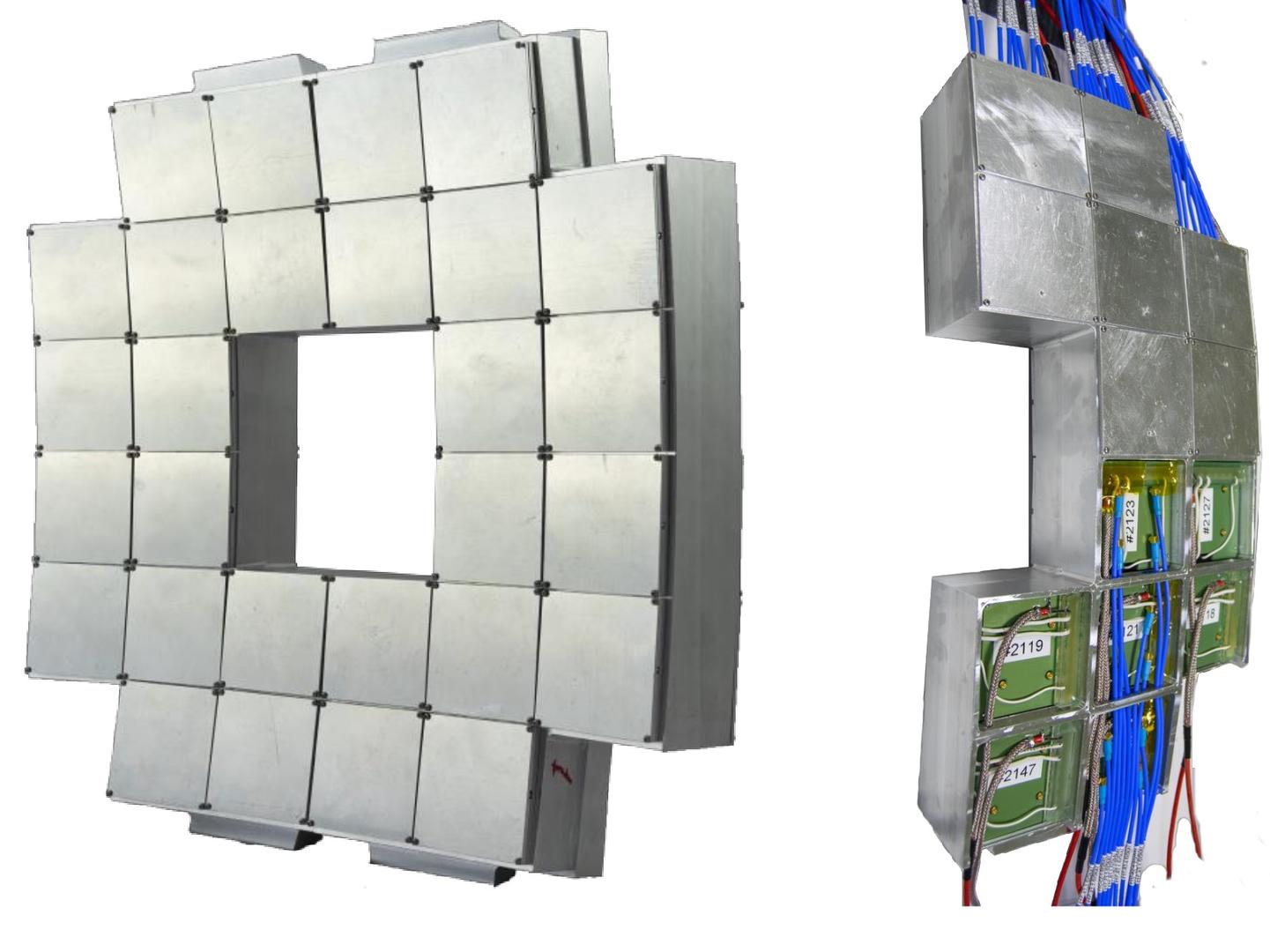
The FT0 consists of two arrays, FT0-A and FT0-C, of quartz Cherenkov radiators optically coupled to factory customized Photonis XP85002/FIT-Q microchannel plate-based (MCP) photomultipliers. The modification is a new back-plane designed specifically for FT0 grouping the 64 anodes into 4 outputs. The 4 independent outputs deliver signals from 4 optically isolated quartz radiators, each 2 cm thick and 2.65 cm by 2.65 cm in area. The signal path from each anode is the same length to improve the timing properties of the system. This segmentation allows for providing the granularity for measurements of multiplicity in central Pb−Pb collisions and has very good coverage of the solid angle subtended by the detector. The intrinsic time resolution of each quadrant is σt ≈ 13 ps. Accounting for signal deterioration along the 30 m long signal cables and processing by the front-end electronics, the achieved one-MIP time resolution of FT0 is about 25 ps. The efficiency of the Minimum Bias trigger for pp collisions is ≥ 98% for the OR of the two sides and ≥ 77% for coincidences between FT0-A and FT0-C. FT0-A, located 3.3 m from the IP has 24 modules and thus 96 individual readout channels. Due to the proximity to the IP, the FT0- C support has a concave shape (as seen from the IP) positioning all 28 MCPs such that each of the 112 quartz radiators is 84 cm from the nominal IP.
FIT FV0
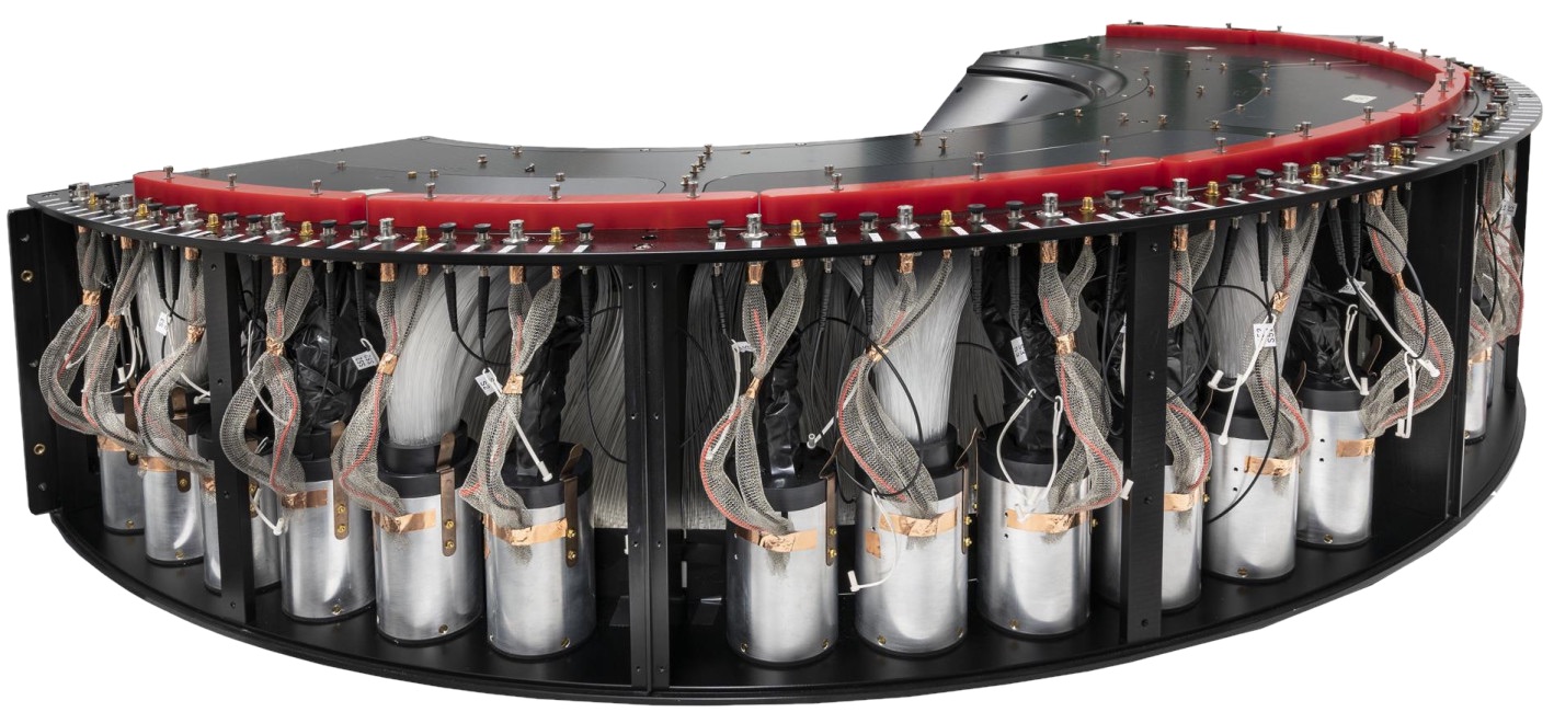
FV0 is a large, segmented scintillator disk with a novel light collection scheme assuring short pulses, single MIP time resolution of ≈ 200 ps, and a very uniform response across the entire detection surface. The active element of FV0 is a 4 cm thick EJ-204 plastic scintillator divided into 5 concentric rings of equal pseudorapidity coverage. The outer diameter of the largest ring is 144 cm and the inner diameter of the smallest is 8 cm. The 4 inner rings are subdivided into 8 sectors of 45 degrees each while the outermost ring, due to its large area, has 16 sectors. A grid of equal-length, clear Asahi fibres is attached to the backside (as viewed from the IP) of the scintillator. At the other end, the fibres from each sector form a bundle and are optically coupled to Hamamatsu R5924-70 PMTs. This way, the 48 sectors of FV0 deliver 48 independent readout channels. This segmentation, combined with the information from the other forward detectors, is sufficient to yield the required centrality and event plane resolution. Together with FT0, FV0 provides the needed input to generate Minimum Bias and Multiplicity trigger at the LM (Level Minus one) level. Having a total latency below 425 ns, this is the fastest trigger in ALICE. The FV0 also monitors LHC background conditions and luminosity.
FIT FDD
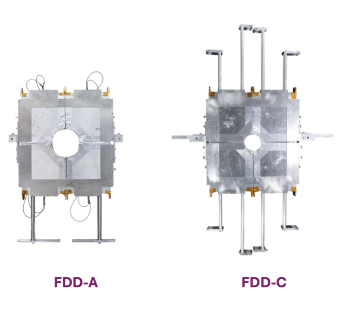
The FDD comprises two nearly identical arrays, FDD-A and FDD-C, surrounding the beam pipe on opposite sides of the IP. Each array consists of eight rectangular BC420 scintillator pads, 216 × 181 x 25mm3. The pads are assembled as two overlapping layers of four sectors each. To make clearance for the beam pipe, a quadrant was removed from the innermost corner of each scintillator plate. The diameter of the quadrant removed from the FDD scintillators is 124 mm on the A-side and 74 mm on the C-side. Each pad has two wavelengths shifting (WLS) bars attached to the opposite sides of the scintillator. Clear optical fibres carry the light from the WLS to H8409-70 PMTs. There are 8 independent FDD channels on each side of the IP.
Benefitting from the much improved ITS capability of heavy flavour tagging in the central barrel, the FDD contributes to the measurements of diffractive cross sections and studies of ultra-peripheral collisions. In pp collisions, the main physics objectives of the FDD are the studies of centrally produced exclusive states, measurements of cross sections for single and double diffraction, and inelastic processes at the new LHC centre of mass energy of 14 TeV. In Pb−Pb and p−Pb collisions, the FDD provides an independent measurement of centrality in an intermediate pseudorapidity range between the ITS and the ZDC and contributes to the selection of ultra-peripheral collisions. In the online mode, the FDD is used to monitor beam quality and to reject beam-gas events.
FIT electronics and readout
All three subsystems of FIT use the same front-end and readout electronics based on just two custom-designed modules: a Processing Module (PM) and a Trigger and Clock Module (TCM). One PM provides 12 independent inputs. Each sub-detector has only one TCM while the number of PMs is determined by the number of channels. Each PM is connected to the dedicated TCM via an HDMI cable to transmit ”pre-trigger” data, slow-control data and LHC clock distribution. The commands, configuration data, and status data are sent from the ALICE control system to the TCMs via a 1 Gb Ethernet optical link using an IPbus (UDP based protocol). The triggers and the measured event rates for the luminosity measurements are transmitted from the TCMs via the same connection. The PMs are configured from TCMs via an HDMI SPI connection. The PMs and TCMs are connected to the ALICE DAQ with GBT links. FIT delivers the produced trigger signals to the Central Trigger System. Laser pulses are used for time and amplitude calibration, as well as monitoring of ageing and radiation damage of the FIT detectors.
FIT installation schedule
-
FT0C – December 2020
-
FDD – February-March 2021
-
FV0 and FT0A – May 2021
Meetings and minutes |
Documentation |
Photos and videosindico link: https://indico.cern.ch/category/12616/ FIT video in ENG: https://videos.cern.ch/record/2298206 FIT video in PL: https://videos.cern.ch/record/2298207 FIT video in RUS: https://videos.cern.ch/record/2298210 FIT video in ES: https://videos.cern.ch/record/2298211 |
Project Management
|
||
Participating Institutes |
||
|
Austria |
Vienna |
Stefan Meyer Institute |
| Czech | Praha |
Technical University of Prague |
| Denmark | Copenhagen |
Niels Bohr Institute, University of Copenhagen |
| Finland |
Jyväskylä |
Helsinki Institute of Physics (HIP) and Univ. of Jyväskylä |
|
Finland |
Helsinki |
Helsinki Institute of Physics (HIP) and Univ. of Helsinki |
| Mexico | Mexico City |
Instituto de Física, UNAM |
| Mexico |
Mexico City |
CINVESTAV |
| Mexico |
Puebla |
Benemérita Universidad Autónoma de Puebla |
| Mexico |
Culiacan, Sinaloa |
Universidad Autónoma de Sinaloa |
| Poland | Krakow |
AGH |
| Poland | Krakow |
IFJ-PAN |
| Poland | Warsaw |
NCBJ |
|
Poland |
Warsaw |
Warsaw University of Technology |
|
Poland |
Katowice |
University of Silesia |
| USA | Chicago |
Chicago State University |
| USA | San Luis Obispo |
California Polytechnic State University |